
Prof. Ali has a column called “Circuit Intuitions” in the IEEE Solid-State Circuits Magazine. This time he wrote about capacitor as a resistor, which is quite helpful for me to understand this property recognized by James Clerk Maxwell 140 years ago. In this post, I tried to write down what I’ve learned from this topic.
First, let’s look at Fig.1 and ask oneself the following question: Between (a) and (b), which one is an integrator and which one is a gain stage?
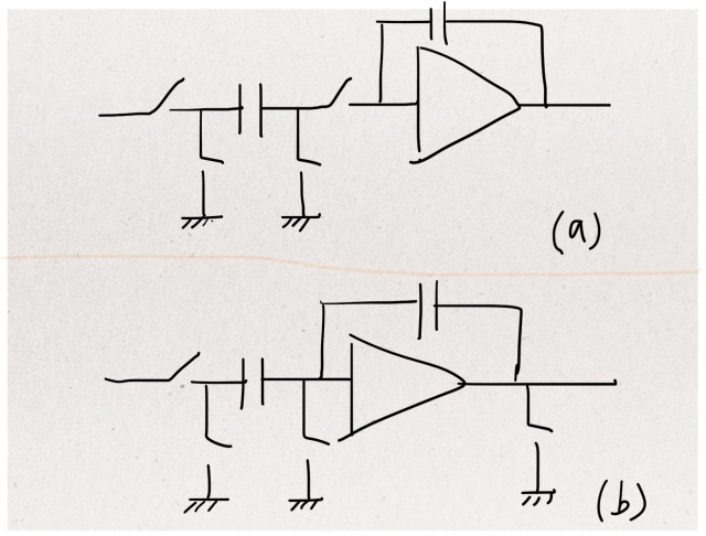
Fig.1 (a) Integrator; (b) Gain stage
The top is an integrator and the bottom a gain stage. The two working modes of the integrator and the gain stage are depicted in Fig.2 and Fig.3, respectively.
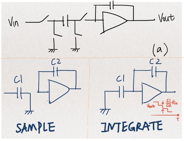
Fig.2 Two modes of integrator: sample and integrate.
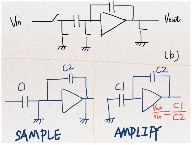
Fig.3 Two modes of gain stage: sample and amplify
Now it’s time to take a close look at the switched-capacitor part of the integrator. Why does it act like a resistor?
First, let’s simplify the parasitic-insensitive version of Fig.4(a) to a straightforward implementation of Fig.4(b). In the first half of the period, S1 is closed and S2 is open. The capacitor is connected to V1, acquiring a charge of Q1=C*V1. In the second half, S1 is closed and S2 is open. The capacitor is connected to V2, storing a charge of Q2=C*V2. During this period, the total charge transferred from V1 to V2 is C*(V1-V2). In the next cycle, the capacitor is again connected to V1, replenishing its charge back to C*V1. Then it transfers a charge of C*(V1-V2) to V2. Accordingly, the average current flowing from source V1 to source V2 is equal to the charge moved in one period:

We can therefore view the discrete-time circuit as a resistor equals to

There are several considerations we shall pay attention to:
- Time varying of V1/V2 should be slower than the rate of switching.
- T/2 should be long enough for the capacitor to fully charge/discharge to the intended levels.
- Different from a resistor, the average currents are the same, but not the instantaneous current.
- … (to be discovered by oneself during real implementation)
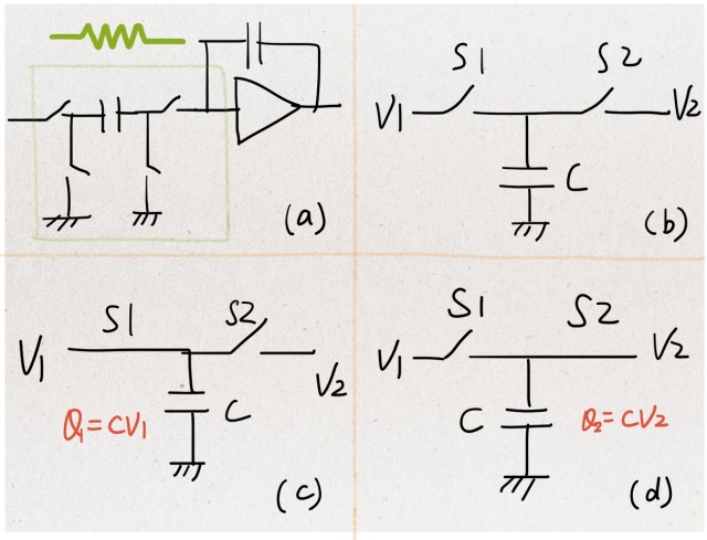
Fig.4: (a) A capacitor and four switches that act like a resistor; (b) A straightforward implementation of (a); (c) S1 is closed and S2 is open; (d) S1 is open and S2 is closed.
Knowing the switched-capacitor version of a resistor, Fig.5 gives two types of integrator: the continuous and the discrete. A comparison between the two reveals one of the advantages of the latter: while the product of R and C may have as much as a 10% process variation, the ratio of two capacitances has only a variation within 0.1%. OK. Let’s also be fair to name one disadvantage of the discrete equivalent: it is jitter-sensitive.
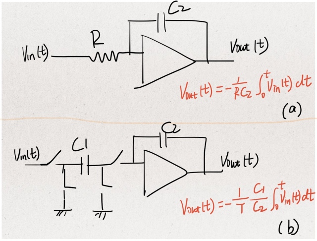
Fig.5 (a) Continuous-time integrator; (b) discrete-time (switched-capacitor) integrator
Finally, allow me to copy part of Prof.Ali’s summary in the article – “If we view a resistor as an element that transfers charge from one terminal to another at a constant rate, we can implement it using a capacitor and two switches.”
